~~~ La versione in italiano inizia subito dopo la versione in inglese ~~~
ENGLISH

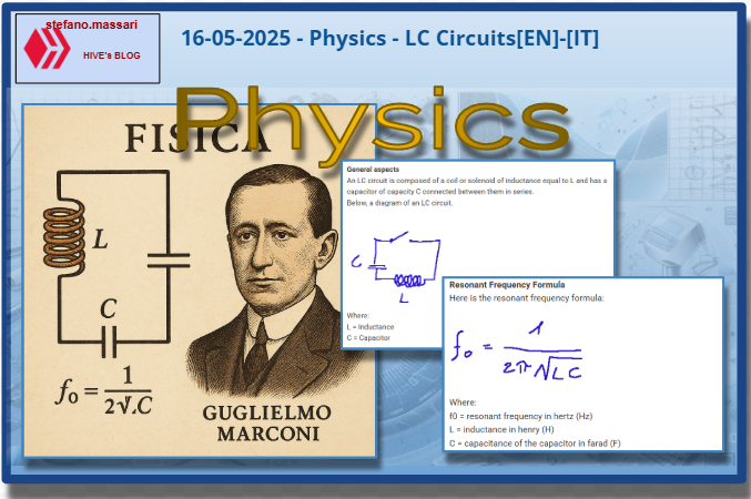
16-05-2025 - Physics - LC Circuits[EN]-[IT]
With this post I would like to give a brief instruction about the topic mentioned in the subject
(code notes: X_18)
LC Circuits
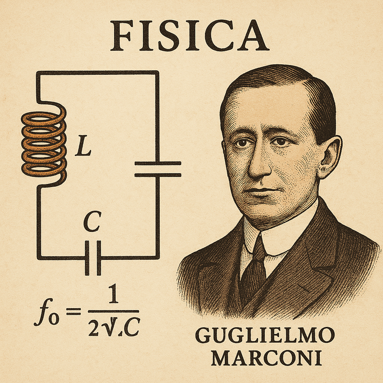
image created with artificial intelligence, the software used is Microsoft Copilot
General aspects
An LC circuit is composed of a coil or solenoid of inductance equal to L and has a capacitor of capacity C connected between them in series.
Below, a diagram of an LC circuit.
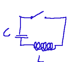
Where:
L = Inductance
C = Capacitor
Note: an inductance is a characteristic that the component called inductor has. It is a physical property of electrical circuits that measures the ability of a conductor to store energy in the form of a magnetic field. The unit of measurement of inductance is the Henry (H).
The capacitor, on the other hand, is an electronic component that stores electrical energy in the form of charge. The capacity is measured in farads (F). When we talk about the capacity of a capacitor, we are essentially talking about how much charge it can store each time it is applied.
In the LC circuit we have an inductor and a capacitor that are put in series. We can say the following. In particular, the inductor L is usually a coil, that is, a winding of conducting wire, capable of storing energy in the magnetic field produced inside it, when it is crossed by a current that does not change over time. Then continuing in the circuit we have the capacitor, represented by the letter C, which instead is an electrical capacity that accumulates electric charge in its plates and stores energy in the electric field that is created between them.
In analog radios, the LC circuit was adjusted to tune to a specific frequency. It allows you to exclude other frequencies so as not to have a disturbed signal.
What magical thing happens in an LC circuit?
Now let's get to the heart of the matter, there is what an LC circuit is capable of doing. From here on I will speak in a technical way, then I will try to describe it in a simpler way.
An LC circuit is an example of an ideal oscillating circuit.
It can store energy based on its resonant frequency. In particular, the capacitor, once charged, inserted in series with the inductance L, charges itself by generating a current that varies over time and in the meantime this current, flowing in the inductance, generates a variable magnetic field inside it.
Using less technical language we can say the following.
An LC circuit is mainly used to manage electrical signals as a function of frequency. These types of circuits can produce sinusoidal oscillations at a very specific frequency. These high frequencies are also used as filters, they allow the passage of certain frequencies and can block others.
Resonant Frequency Formula
Here is the resonant frequency formula:
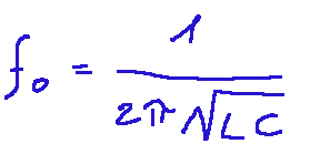
Where:
f0 = resonant frequency in hertz (Hz)
L = inductance in henry (H)
C = capacitance of the capacitor in farad (F)
One of the main characteristics of an LC circuit is what is called the resonant frequency. The resonant frequency represents the point at which the circuit responds with maximum efficiency to electrical oscillations.
Why do we calculate and search for this resonant frequency?
At this resonant frequency, in our LC circuit, interesting things happen, here they are listed below:
-in series circuits the impedance is minimum
-in parallel circuits the impedance is maximum
-a strong amplification of the signal is created. This is due to the fact that the energy oscillates between the inductor and the capacitor.
-at the resonant frequency we can maximize the energy transfer. This happens in wireless charging circuits.
Who worked first on LC circuits
Here we have some very well-known names. Among those who experimented with LC circuits are:
-Heinrich Hertz (1857–1894)
-Nikola Tesla (1856–1943)
-Lord Kelvin (1824–1907)
-Guglielmo Marconi (1874–1937)
Conclusions
LC circuits arose from the development of the theory of electromagnetism and are the simplest example of an oscillating circuit.
Question
Did you know that the Italian Guglielmo Marconi was a practical pioneer in the use of LCs in telecommunications? Did you also know that he applied resonant LC circuits to create long-distance radio?
![]()
ITALIAN

16-05-2025 - Fisica - Circuiti LC[EN]-[IT]
Con questo post vorrei dare una breve istruzione a riguardo dell’argomento citato in oggetto
(code notes: X_18)
Circuiti LC
immagine creata con l’intelligenza artificiale, il software usato è Microsoft Copilot
Aspetti generali
Un circuito LC è composto da una bobina o solenoide di induttanza pari a L ed ha un condensatore di capacità C tra di loro collegati in serie.
Qui di seguito, uno schema di un circuito LC.
Dove:
L = Induttanza
C = Condensatore
Nota: un’induttanza è una caratteristica che ha il componente chiamato induttore. Essa è una proprietà fisica dei circuiti elettrici che misura la capacità di un conduttore di immagazzinare energia sottoforma di campo magnetico. L’unità di misura dell’induttanza è l’Henry (H).
Il condensatore invece è un componente elettronico che immagazzina energia elettrica sottoforma di carica.la capacità si misura in farad (F). Quando parliamo della capacità di un condensatore sostanzialmente parliamo di quanta carica può immagazzinare per ogni volta applicato.
Nel circuito LC abbiamo punto un induttore e un condensatore che sono messi in serie. Possiamo dire quanto segue. In particolare l’induttore L solitamente è una bobina, cioè un avvolgimento di filo conduttore, capace di immagazzinare energia nel campo magnetico prodotta al suo interno, quando è percorsa da una corrente invariabile nel tempo. Poi proseguendo nel circuito abbiamo il condensatore, rappresentato dalla lettera C, che invece è una capacità elettrica che accumula carica elettrica nelle sue armature e immagazzina energia nel campo elettrico che si viene a creare tra di esse.
Nelle radio analogiche il circuito LC veniva regolato per sintonizzarsi su una frequenza specifica. Esso permette di escludere le altre frequenze in modo da non avere un segnale distrurbato.
Cosa avviene di magico in un circuito LC?
Ora entriamo nel vivo della questione, c’è di che cosa è in grado di fare un circuito LC. Da qui in poi parlerò in maniera tecnica, poi cercherò di descriverlo in maniera più semplice.
Un circuito LC è l’esempio di un circuito oscillante ideale.
Esso può immagazzinare energia in base alla sua frequenza di risonanza. In particolare il condensatore una volta carico, inserito in serie con l’induttanza L, si carica generando una corrente variabile nel tempo e nel frattempo tale corrente, scorrendo nell’induttanza, genera in essa un campo magnetico variabile al suo interno.
Usando un linguaggio meno tecnico possiamo dire quanto segue.
Un circuito LC serve principalmente per gestire segnali elettrici in funzione della frequenza.queste tipologie di circuito possono produrre oscillazioni sinusoidali a una frequenza ben precisa. Questi acuti vengono usati anche con la funzione di filtro, essi permettono il passaggio di determinate frequenze e possono bloccarne invece altre.
Formula della frequenza di risonanza
Qui di seguito è descritta la formula della frequenza di risonanza:
Dove:
f0 = frequenza di risonanza in hertz (Hz)
L = induttanza in henry (H)
C = capacità del condensatore in farad (F)
Una delle caratteristiche principali di un circuito LC è quella che viene chiamata frequenza di risonanza. La frequenza di risonanza rappresenta il punto in cui il circuito risponde con la massima efficienza alle oscillazioni elettriche.
Perché si calcola e si cerca questa frequenza di risonanza?
A questa frequenza di risonanza, nel nostro circuito LC, avvengono cose interessanti, eccole qui di seguito elencate:
-nei circuiti in serie l’impedenza è minima
-nei circuiti in parallelo l’impedenza è massima
-si viene a creare una forte amplificazione del segnale. Questo al fatto che l’energia oscilla tra l’induttore e il condensatore.
-alla frequenza di risonanza possiamo massimizzare il trasferimento di energia. Questo avviene nei circuiti wireless di ricarica.
Chi ha lavorato per primo sui circuiti LC
Qui abbiamo dei nomi molto conosciuti. Tra quelli che hanno sperimentato i circuiti LC troviamo:
-Heinrich Hertz (1857–1894)
-Nikola Tesla (1856–1943)
-Lord Kelvin (1824–1907)
-Guglielmo Marconi (1874–1937)
Conclusioni
I circuiti LC sono nati dallo sviluppo della teoria dell’elettromagnetismo ed essi sono l’esempio più semplice di circuito oscillante.
Domanda
Lo sapevate che l’italiano Guglielmo Marconi fu un pioniere pratico nell’uso di LC in telecomunicazioni? Sapevate anche che egli applicò proprio i circuiti LC risonanti per creare la radio a lunga distanza?
THE END