Greetings to the DIY community, I hope you have a great week and I wish you much encouragement to get ahead in the situation that life has placed you in, (as you know, sometimes life goes a little overboard, raising the level of difficulty)

Anyone in a workshop has already experienced this particular situation, where the equipment arrives completely disassembled, either from another workshop that could not do the work or from the client who cannot get the device to work and brings it to you completely disassembled in parts.
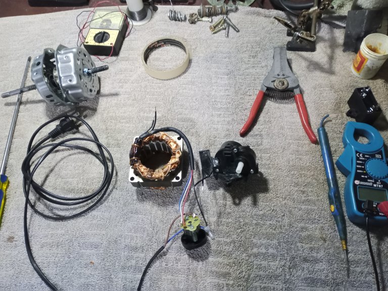
I received a three-speed home fan completely disassembled and I decided to make a small guide on how to check this type of device and know if it is worth repairing or buying another fan, since they are very cheap these days.
We will need few tools, but it will be necessary to have a minimum of basic knowledge to do the inspection of the equipment.
- A tester or a continuity and resistance tester.
- Screwdriver according to the type of screw the motor is assembled with (Philips, Torx, flat, etc.)
- A capacitance meter (some testers have this function built in)
- Long-nose pliers and side-cutting pliers.
- Soldering iron, solder paste, solder.
- A piece of 100 or 80 grit sandpaper.
If you do not have the basic minimum knowledge of electricity, I strongly recommend that you do not try to manipulate machinery, tools or appliances.
These instructions are for a domestic fan with three speeds.
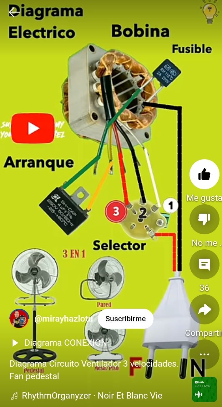
Video frame source:
https://www.youtube.com/shorts/SUDo0iREpHM
This image is quite practical, it saves me a bit from having to make my own version, it serves well to get an idea of the connections, before seeing the electrical circuit. (if you can please give a like to the mini video, it is very well done)
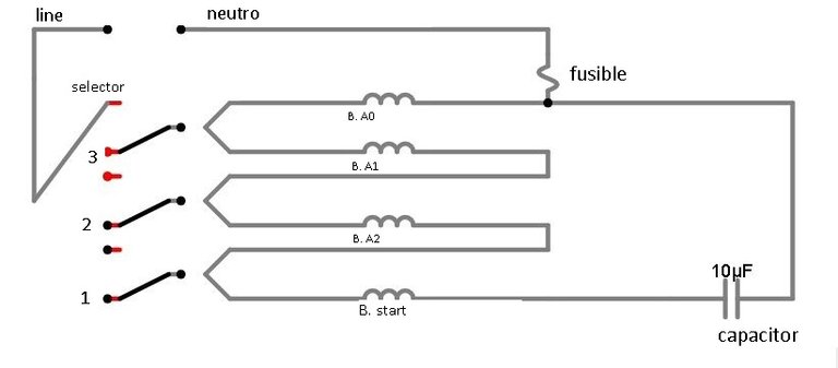
The circuit diagram of this motor would be:
The first thing to check in all electrical equipment is to measure that the power cable is in good condition, work with the equipment disconnected from the electrical network and make sure to discharge the motor capacitor.
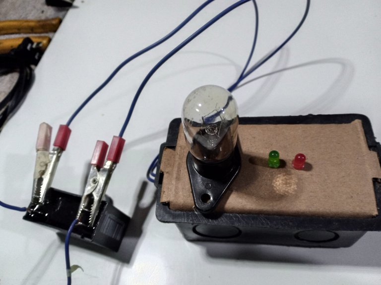
I use a tool to discharge circuits, cards and capacitors, made with a 110 Volt microwave bulb.
You can see the publication of this tool at: Capacitor Downloader
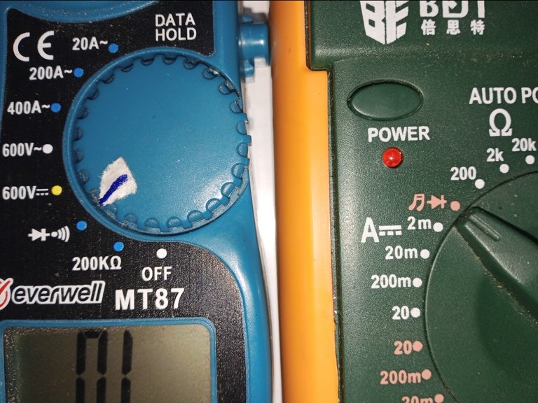
We will place the tester on the continuity meter with the option of the buzzer or diodes.
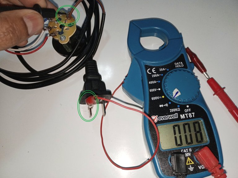
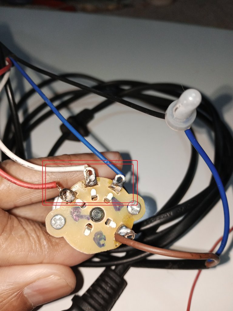
To test the plug cable:
One of the plug pins or sockets goes directly to the common point of the gear selector, verifying that there is continuity between both ends, to ensure that it is not damaged.
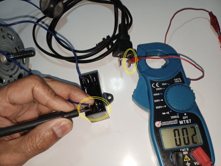
The other pin or plug goes directly to one of the ends of the capacitor, only to one of the ends, at that end goes the thermal fuse that protects the motor. If there is no continuity, it is very possible that the thermal fuse connected to the cable is damaged. And if there is continuity between the plug pin and either end of the capacitor, it is very possible that the capacitor is damaged.
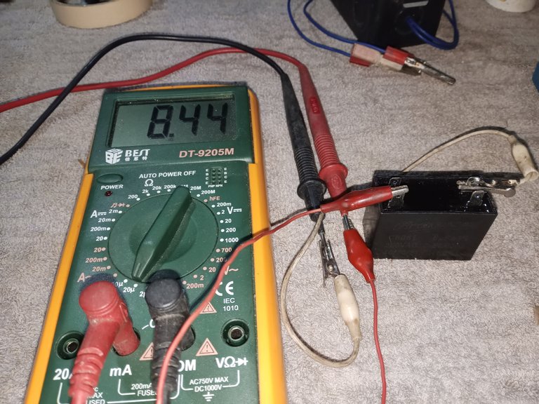
In these domestic fans, the most common fault is that the capacitor has been damaged, we must always be sure that it is discharged before working with it and then measure it with a capacitance meter.
It must be replaced with one of the same capacity, not a higher or lower capacity.
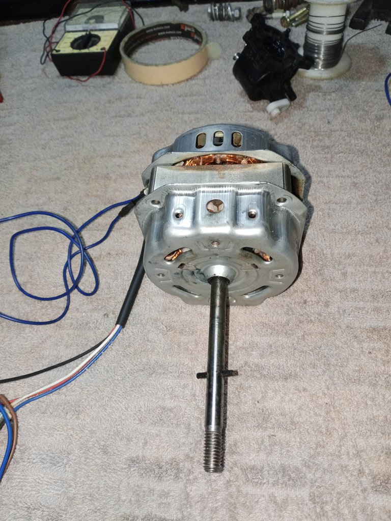
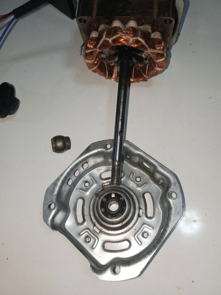
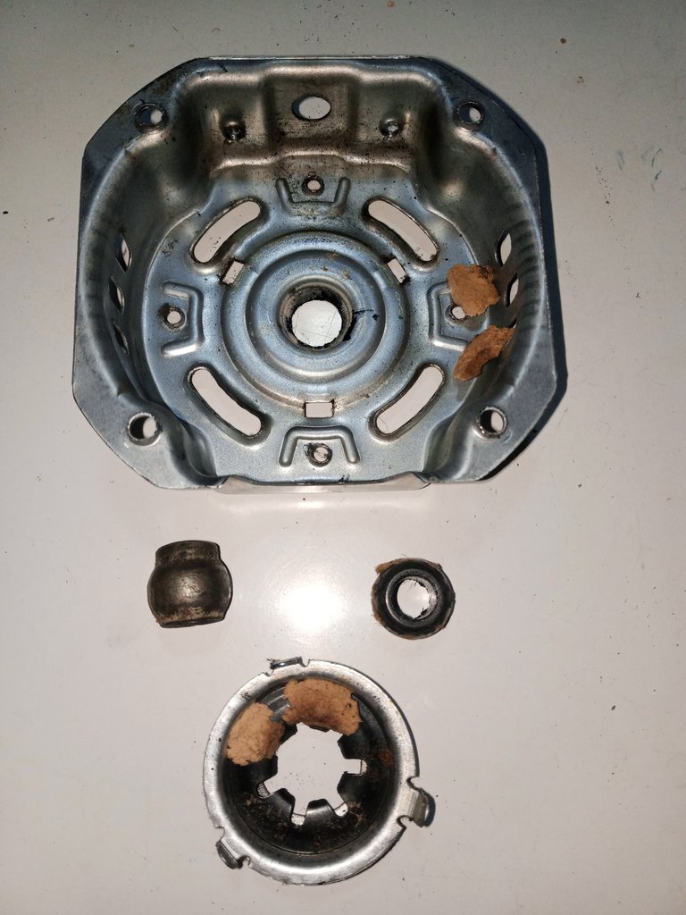
The other most common fault in domestic fans is that the horns that go on the end caps of the motor have suffered a lot of wear, in these cases you feel vibration in the motor, when trying to start it, but the shaft does not turn.
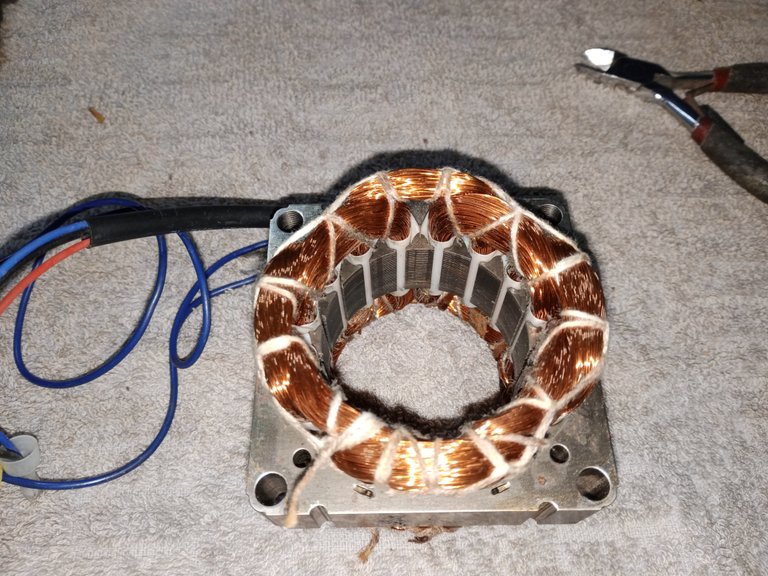
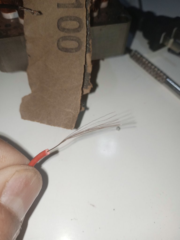
These fans are wound with aluminum wire and it is the insulating varnish that gives it the copper color. Aluminum wire is quite fragile and must be handled very carefully, it cannot be soldered as easily as we solder wire made of copper.
With the fan selector off, we measure that there is continuity between the speeds to be sure that they are not interrupted.

The speeds must have continuity between any point where they are measured, they are connected in series, if one of the three does not have continuity the circuit is open, if the connection is damaged a little more advanced work will be required.
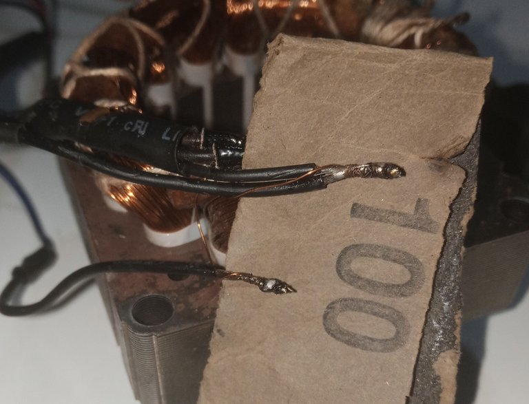
On this fan motor I changed the horns, the capacitor was also damaged and I had to solder the connections that go from the capacitor to the coils.
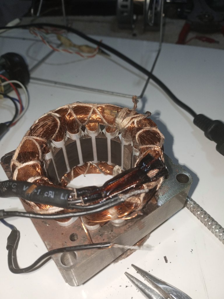
The aluminum wire was broken at its tips and the solders on the copper wires were sulfated, the aluminum wire was coiled and not soldered on the copper wire, there was no good connection.
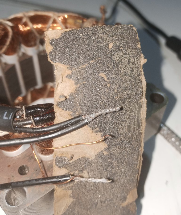
To solder aluminum and copper there are several tricks, the simplest method, which does not require special ingredients, requires that the materials be cleaned well, and the varnish be sanded off the wires, and then spliced again.
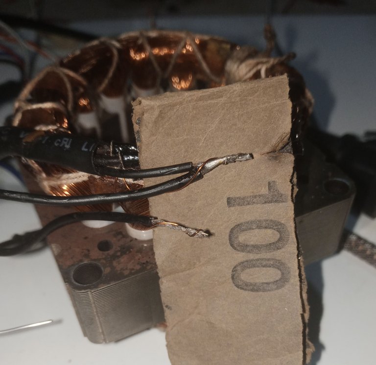
We managed to get some wires from a piece of recycled cable, to wrap around the splice of the aluminum and copper wires.
We put the respective copper soldering paste and solder it on the copper wire wound on the aluminum and copper joint.
Despite all the work, the coils were already damaged, when measuring between the ends of the capacitor wires there is a resistance of about 320 ohm to 350 ohm. Therefore it was not worth taking it apart any more, everything possible was done to repair it, but not all cases can be solved, it is a law of life.
However, I hope it serves as a reference if, at some point, you need some insight into how to check a three-speed fan motor.
Thank you very much for stopping by and reading me.
Have a great week.
Peace.
- I used Google Translate for English.
- I used TextStudio app for Spanish banner.
- I used masterplc online program for circuit diagram.
- Images unless otherwise noted are from my work in the workshop.
- I used NightCafe program to create player image.

Saludos a la comunidad DIY, espero que tengan una excelente semana y les deseo mucho ánimo para salir adelante en la situación en que la vida les haya colocado, (que como ya saben que algunas veces, la vida se pasa un poco de la raya, subiendo el nivel de dificultad)
Cualquiera en un taller ya ha vivido esta situación particular, en que el equipo llega todo desarmado, ya sea por otro taller que no pudo hacer el trabajo o por el cliente que no consigue hacer andar el aparato y te lo trae todo desarmado por partes.
Me ha llegado un ventilador casero de tres velocidades totalmente desmontado y me propuse hacer una pequeña guía de como revisar este tipo de artefacto y saber si vale la pena la reparación o comprar otro ventilador, ya que hoy día son muy económicos.
Necesitaremos pocas herramientas, pero sí que será necesario que tengan un mínimo de conocimientos básicos para hacer la inspección del equipo.
- Un tester o un probador de continuidad y resistencias.
- Destornillador según el tipo de tornillo con el que esté armado el motor (Philips, torx, plano, etc.)
- Un capacímetro (algunos tester tienen incorporada la función)
- pinzas de puntas largas y alicates de corte lateral.
- Soldador de estaño, pasta para soldar, estaño.
- Un trozo de lija número 100 o número 80.
Si no tiene los conocimientos mínimos básicos de electricidad, le voy a recomendar encarecidamente que no traten de manipular maquinaria, herramientas o artefactos.
Estas indicaciones son para un ventilador doméstico con tres velocidades.
Fuente del fotograma de video: https://www.youtube.com/shorts/SUDo0iREpHM
Esta imagen es bastante práctica, me ahorra un poco hacer mi propia versión, sirve bien para hacerse una idea de las conexiones, antes de ver el circuito eléctrico. (si pueden por favor den un like al mini video, está muy bien hecho)
El diagrama del circuito de este motor sería:
Lo primero a revisar en todo equipo eléctrico, es medir que el cable de alimentación eléctrica que esté en buen estado, se trabaja con el equipo desconectado de la red eléctrica y nos aseguramos de descargar el capacitor del motor.
Yo uso una herramienta para descargar circuitos, tarjetas y capacitores, hecho con un bombillo de microondas de 110 Volts.
La publicación de esta herramienta la puedes ver en: Descargador de capacitores
Colocaremos el tester en el medidor de continuidad con la opción del timbre o diodos.
Para probar el cable del enchufe:
Uno de los pines o de las clavija del enchufe va directamente al punto común del selector de velocidades, se verifica que haya continuidad entre ambos extremos, para asegurarse de que no está dañado.
El otro pin o clavija del enchufe va directamente a uno de los extremos del capacitor, solo a uno de los extremos, en ese extremo va el fusible térmico que protege al motor. Si no hay continuidad, es muy posible que el fusible térmico conectado al cable, este dañado. Y si hay continuidad entre el pin del enchufe y cualquiera de los dos extremos del capacitor, es muy posible que el capacitor esté dañado.
En estos ventiladores domésticos, la falla más común es que el capacitor se haya dañado, tenemos como siempre que estar seguro de que esté descargado antes de trabajar con él y luego medirlo con un capacímetro.
Se debe cambiar por uno de la misma capacidad, no colocar una capacidad mayor o menor.
La otra falla más común de los ventiladores domésticos es que las bocinas que van en las tapas de los extremos del motor, hayan sufrido mucho desgaste, en esos casos se siente vibración en el motor, al tratar de hacerlo arrancar, pero el eje no gira.
Estos ventiladores están bobinados con alambre de aluminio y es el barniz aislante, el que le da el color del cobre. El alambre de aluminio es bastante frágil y debe manipularse con mucho cuidado, no se puede soldar con la misma facilidad con la que soldamos el alambre hecho de cobre.
Con el selector del ventilador apagado medimos que haya continuidad entre las velocidades para estar seguros de que no estén interrumpidas.
Las velocidades deben tener continuidad entre cualquier punto en que se mida, están conectadas en serie, si una de las tres no tiene continuidad el circuito está abierto, si está dañada la conexión se requerirá un trabajo un poco más avanzado.
En este motor de ventilador cambié las bocinas, el capacitor estaba también dañado y tuve que soldar las conexiones que van del capacitor a las bobinas.
El alambre de aluminio estaba roto en sus puntas y las soldaduras de los cables de cobre estaban sulfatadas, el alambre de aluminio estaba enrollado y no estaba soldado en el cable de cobre, no había una buena conexión.
Para soldar el aluminio y el cobre hay varios trucos, el método más simple, que no se necesita de ingredientes especiales, requiere que se limpie bien los materiales, y se lije el barniz de los alambres, para luego volver a empalmarlos.
Conseguimos sacar algunos alambres de un trozo de cable reciclado, para enrollar sobre el empalme de los alambres de aluminio y cobre.
Colocamos la respectiva pasta para soldar cobre de siempre y soldamos sobre el alambre de cobre enrollado sobre el empalme de aluminio y cobre.
A pesar de todo el trabajo, las bobinas ya estaban dañadas, al medir entre los extremos de los cables de capacitor tiene que haber una resistencia de unos 320 ohm a 350 ohm. Por lo que ya no valía la pena seguir desarmando, se hizo lo más posible por repararlo, pero no todos los casos pueden resolverse, es una ley de la vida.
Sin embargo, espero que les sirva como referencia si es que, en algún momento, necesitan alguna una noción para revisar un motor de ventilador de tres velocidades.
Muchas gracias por pasar y leerme.
Que tengan una excelente semana.
Paz.
- He usado el traductor de Google para el inglés.
- He usado la aplicación de TextStudio para el banner en español.
- He usado el programa en línea masterplc para el diagrama del circuito.
- Las imágenes a menos que se indique son de mi trabajo en el taller.
- He usado el programa NightCafe para crear la imagen del jugador.