~~~ La versione in italiano inizia subito dopo la versione in inglese ~~~
ENGLISH

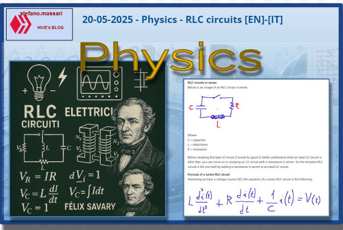
20-05-2025 - Physics - RLC circuits [EN]-[IT]
With this post I would like to give a brief instruction about the topic mentioned in the subject
(code notes: X_16)
RLC circuits
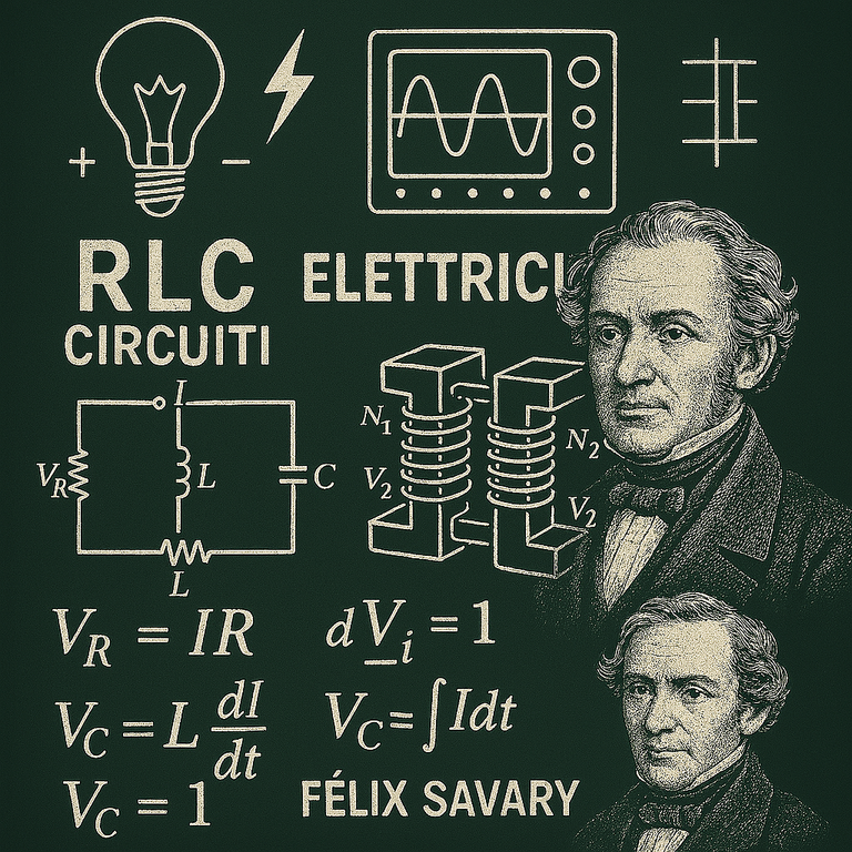
image created with artificial intelligence, the software used is Microsoft Copilot
RLC circuits in series
Below is an image of an RLC circuit in series

Where:
C = capacitor
L = inductance
R = resistance
Before studying this type of circuit, it would be good to better understand what an ideal LC circuit is. After that, you can move on to studying an LC circuit with a resistance in series. So the simplest RLC circuit is the one built by adding a resistance in series to an ideal LC circuit.
Formula of a series RLC circuit
Assuming we have a voltage source V(t), the equation of a series RLC circuit is the following:
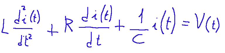
Where:
L = the inductance (in Henry, H)
R = the resistance (in Ohm, Ω)
C = the capacitance (in Farad, F)
V(t) = applied voltage
i(t) = the current over time
The AC powered RLC circuits
The importance of these circuits is especially with an AC power supply.
Below is a diagram to be clearer.
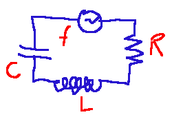
Where:
R = resistance that dissipates energy in the form of heat
L = inductance, which opposes variations in current
C = Capacitance that opposes variations in voltage.
f = power supply of a sinusoidal source
In RLC circuits each component has an impedance. Usually the impedance is described with a Z. The impedance is the quantity that generalizes the electrical resistance in alternating current (AC) circuits.
Power in an RLC circuit
First of all, let's talk about the power factor.
The power factor cosφ measures how much of the supplied electrical power is actually used for useful work (active energy) compared to the total power.
Below is the formula
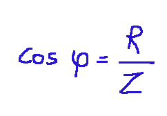
Where:
cosφ = power factor of the circuit
R = resistance
Z = total impedance of the circuit
Why is it important to know the power factor?
Because it immediately gives us a piece of data:
if cosφ = 1, it means that all the power is useful and therefore we are faced with a purely resistive circuit.
if cosφ < 1, we already know that a part of the power will be reactive
Active power
Now we can better understand the formula for the active power of an RLC circuit crossed by alternating current.
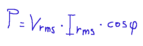
Where:
Vrms = effective voltage
Irms = effective current
cosφ = power factor
Basically this formula gives us a very important result because it tells us how much the real power is, that is, the power that is actually consumed by the circuit. Power that can be used to produce heat, light or movement.
Transformers
The ideal transformer is a system of two windings, one called primary and one secondary, on an iron core, isolated from each other and composed of Np and Ns turns.
What happens in a transformer?
The primary circuit, purely inductive, is connected to an alternating generator and does not dissipate power. Through the iron core, the magnetic field and in particular its flux is transmitted from one winding to the other without variation.
Both RLC circuits and transformers are very important devices for alternating current applications. Both RLC circuits and transformers exploit the phenomenon of electromagnetic induction.
The first transformer was designed by three Hungarian engineers who worked together on the project. It was 1885 when Károly Zipernowsky, Ottó Bláthy, Miksa Déri, demonstrated that it was possible to transmit electrical energy in AC with high efficiency, transforming the voltage without significant losses.
Conclusions
RLC circuits are a very important topic in the electrical and electronic fields because they have a good ability to model and control the behavior of electrical signals. With RLC circuits we can control frequencies, we can manage resonance phenomena, model transistors, study impedances. We find them in televisions, audio systems, smartphones, medical instruments and in the various devices used in industrial automation.
Question
Did you know that one of the first to observe the behavior of these circuits was Felix Savary using a Leyden jar (one of the first capacitors) and an iron wire wrapped around it? It was 1826, on that occasion Savery noticed that the electric discharge could invert the magnetization of an iron needle, indicating the presence of oscillating currents.
Did you know that inventors like Savary laid the foundations for the construction of TV and radio components?
![]()
ITALIAN

20-05-2025 - Fisica - I circuiti RLC [EN]-[IT]
Con questo post vorrei dare una breve istruzione a riguardo dell’argomento citato in oggetto
(code notes: X_16)
I circuiti RLC
immagine creata con l’intelligenza artificiale, il software usato è Microsoft Copilot
Circuiti RLC in serie
Qui di seguito un immagine di un circuito RLC in serie
Dove:
C = condensatore
L = induttanza
R = resistenza
Prima di studiare questa tipologia di circuiti sarebbe bene comprendere meglio che cos’è un circuito LC ideale. Dopodiché si può passare allo studio di un circuito LC con in serie una resistenza. Quindi il circuito RLC più semplice è quello costruito aggiungendo una resistenza in serie ad un circuito LC ideale.
Formula di un circuito RLC in serie
Ipotizzando di avere una sorgente di tensione V(t), l'equazione di un circuito RLC in serie è la seguente:
Dove:
L = l’induttanza (in Henry, H)
R = la resistenza (in Ohm, Ω)
C = la capacità (in Farad, F)
V(t) = tensione applicata
i(t) = la corrente nel tempo
I circuiti RLC alimentati in alternata
L’importanza di questi circuiti è soprattutto con un'alimentazione a corrente alternata.
Qui sotto uno schema per essere più chiari.
Dove:
R = resistenza che dissipa energia sotto forma di calore
L = induttanza, che si oppone a variazioni di corrente
C = Capacità che si oppone a variazione di tensione.
f = alimentazione di una sorgente sinusoidale
Nei circuiti RLC ogni componente ha un impedenza. Di solito l’impedenza è descritta con una Z. L’impedenza è la grandezza che generalizza la resistenza elettrica nei circuiti in corrente alternata (AC).
La potenza in un circuito RLC
Innanzitutto parliamo del fattore di potenza.
Il fattore di potenza cosφ misura quanto la potenza elettrica fornita viene effettivamente utilizzata per lavoro utile (energia attiva) rispetto alla potenza totale.
Qui di seguito la formula
Dove:
cosφ = fattore di potenza del circuito
R = resistenza
Z = impedenza totale del circuito
Perché è importante conoscere il fattore di potenza?
Perché ci da subito un dato:
se cosφ = 1, significa che tutta la potenza è utile e quindi siamo di fronte ad un circuito puramente resistivo.
se cosφ < 1, sappiamo già che una parte della potenza sarà reattiva
La potenza attiva
Ora possiamo comprendere meglio la formula della potenza attiva di un circuito RLC attraversato dalla corrente alternata.
Dove:
Vrms = tensione efficace
Irms = corrente efficace
cosφ = fattore di potenza
Sostanzialmente questa formula ci da un risultato molto importante perché ci dice quanto è la potenza reale, cioè quella che viene effettivamente consumata dal circuito. Potenza che può servire per produrre calore, luce o movimento.
Trasformatori
Il trasformatore ideale è un sistema di due avvolgimenti, uno denominato primario e uno secondario, su un nucleo di ferro, isolati tra loro e composti da Np e Ns spire.
Cosa succede in un trasformatore?
Il circuito primario, puramente induttivo, è connesso ad un generatore alternato e non dissipa potenza. Tramite il nucleo di ferro, il campo magnetico e in particolare il suo flusso viene trasmesso da un avvolgimento all’altro senza variazione.
Sia i circuiti RLC che i trasformatori sono dispositivi molto importanti per le applicazioni in corrente alternata. Sia i circuiti RLC e i trasformatori sfruttano il fenomeno dell’induzione elettromagnetica.
Il primo trasformatore fu ideato da tre ingegneri ungheresi che lavorarono insieme al progetto. Era il 1885 quando Károly Zipernowsky, Ottó Bláthy, Miksa Déri, dimostrarono che era possibile trasmettere energia elettrica in AC con alta efficienza, trasformando la tensione senza perdite significative.
Conclusioni
I circuiti RLC rappresentano un argomento molto importante in ambito elettrotecnico ed elettronico perché hanno una buona capacità di modellare e controllare il comportamento dei segnali elettrici. Con i circuiti RLC si possono controllare le frequenze, possiamo gestire i fenomeni di risonanza, modellare i transistori, studiare le impedenze. Li troviamo nelle televisioni, sistemi audio, smartphone, strumenti medici e negli svariati dispositivi che si usano nell’automazione industriale.
Domanda
Lo sapevate che tra i primi ad osservare il comportamento di questi circuiti fu Felix Savary utilizzando una bottiglia di Leida (uno dei primi condensatori) e un filo di ferro avvolto attorno ad essa? Era il 1826, in quell’occasione Savery notò che la scarica elettrica poteva invertire la magnetizzazione di un ago di ferro, indicando la presenza di correnti oscillanti.
Lo sapevate che inventori come Savary gettarono le basi per la costruzione dei componenti delle TV e delle radio?
THE END